




Instrument · airborne EM survey
HoriZOND EM
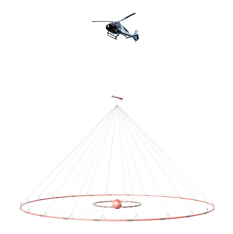
HoriZOND EM — a multipurpose helicopter-borne electromagnetic survey system.
Helicopter-borne time-domain electromagnetic (TEM) survey system. Secondary-field measurements are used for 1D and 3D inversion that accounts for induced polarisation.
System configuration
up to 500 mdepth of investigation
5 msounding interval
take-off mass
300 000A·m² · dipole moment
Applications
Geological tasks
Mineralisation and kimberlitesSulphide, porphyry copper and polymetallic mineralisation and kimberlite bodies — conductive targets and targets with resistivity contrast.
Ore-controlling tectonicsFault and contact zones that define fluid pathways and the emplacement of mineralisation.
AquifersDelineation of aquifers and water-saturated zones by resistivity.
PermafrostMapping of frozen ground and taliks: high-resistivity response and the talik–permafrost boundary.
Palaeovalleys and karstConductive unconsolidated fill of erosional incisions and karst zones in the section.
How it works
Transient measurement
After the current in the transmitter loop is switched off, the decay of the secondary field is recorded. The recording time windows are related to the depth of investigation.
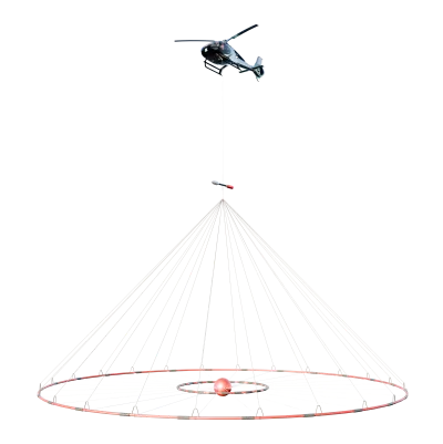
Pulse in the loopA trapezoidal current in the transmitter loop excites the primary field. The dipole moment of the loop is up to 300 000 A·m².
Recording after current switch-offAfter switch-off the receiver coil records only the secondary field — the response of the ground, without primary-field coupling.
Time gatesThe decay curve is analysed by time windows. Early windows characterise shallower depths, late ones greater depths; depth depends on time and on ground resistivity.
1D and 3D inversionThe decay curves are inverted in 1D and 3D, accounting for induced polarisation, to build a model of the section.
Resolution
Sounding interval
The sounding interval is 5 m.
Sparse gridWith a large sounding interval, a local anomaly may lie between measurement points.
5 m intervalAirborne soundings are made at a 5 m interval.
Geometry
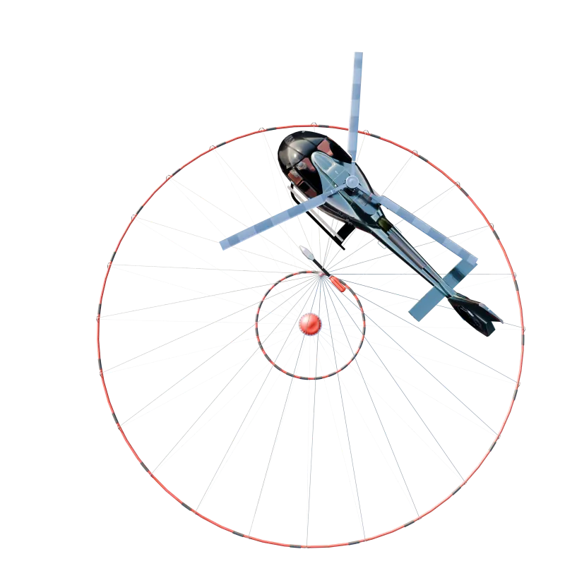
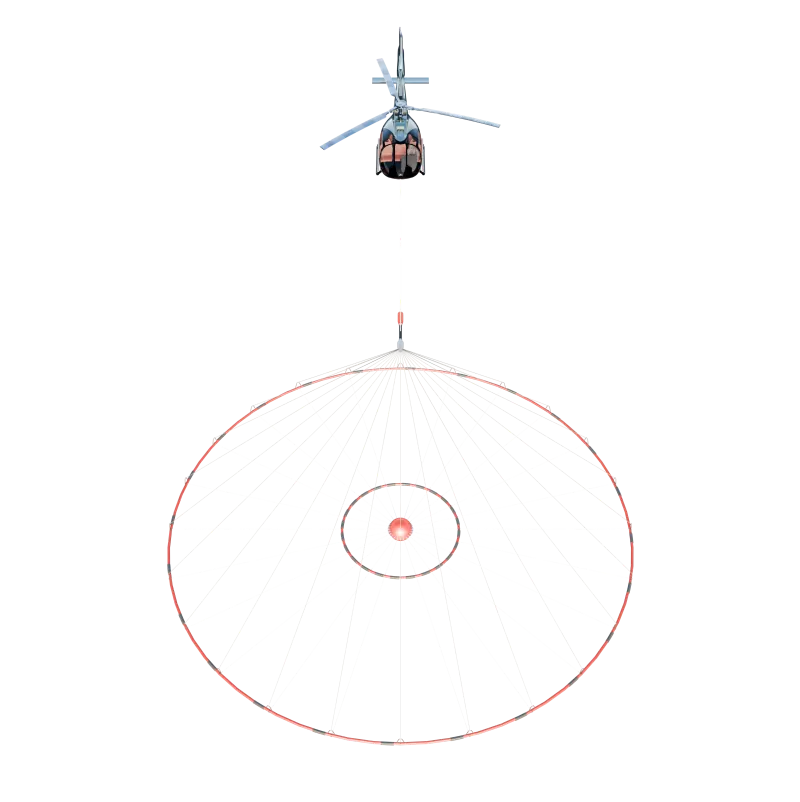
Coaxial loop
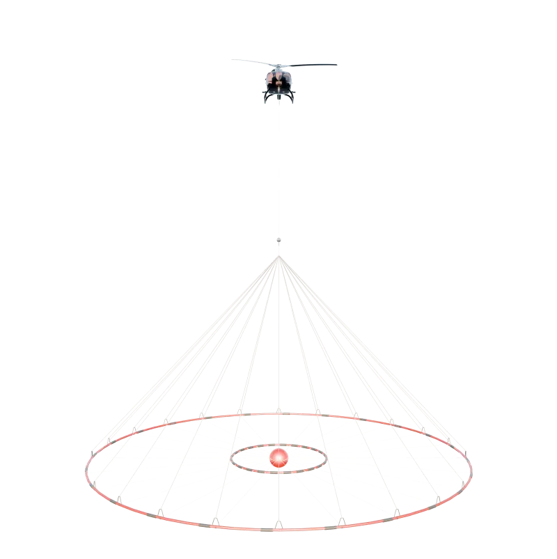
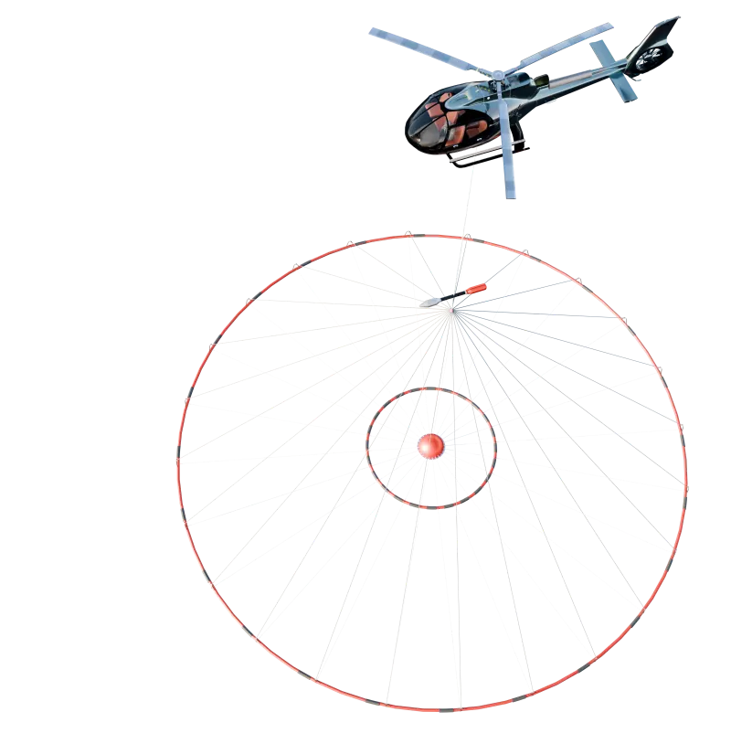
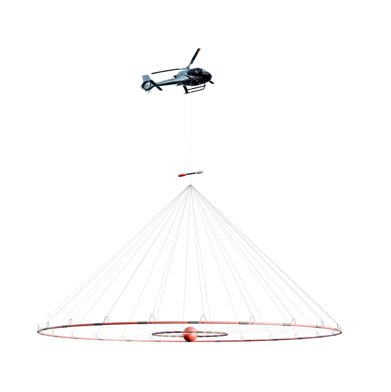
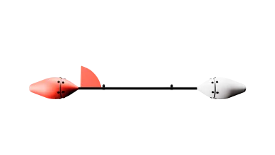
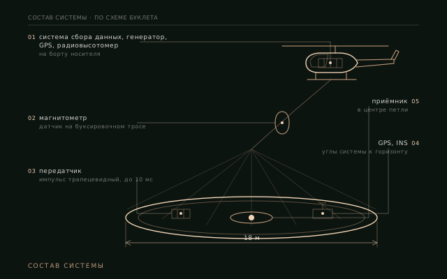
The receiver coil is located at the centre of the transmitter loop.
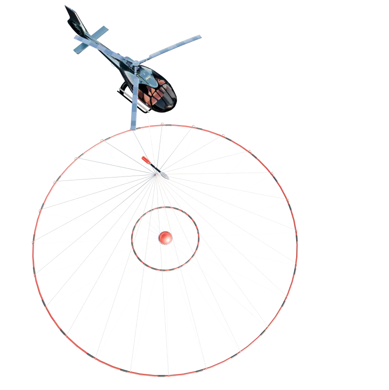
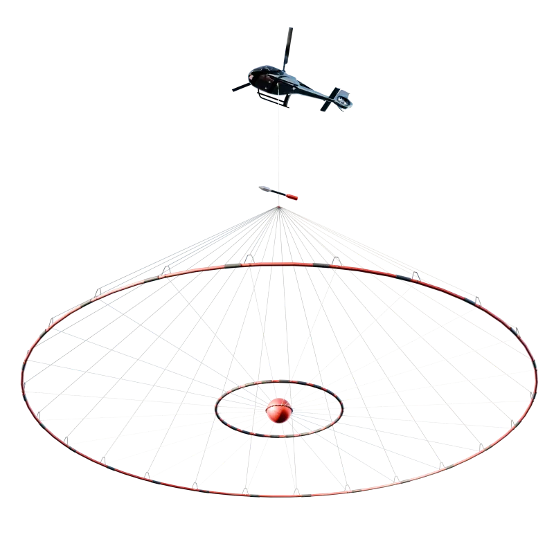
Offset receiver coilThe receiver coil is located behind and above the transmitter loop.
Coaxial configurationThe receiver coil is located at the centre of the loop. Damping is intended to reduce noise when recording at late times.
Specifications
Specifications
| Parameter | Value |
|---|---|
| depth of investigation | up to 500 m |
| recorded components | X, Y, Z |
| base frequency | 25 / 75 Hz |
| transmitter loop diameter | 18 m |
| sampling rate | 250 kHz |
| dipole moment | up to 300 000 A·m² |
| receiver coil noise level | 0.2 nT/s |
| flight speed | up to 170 km/h |
| pulse shape | trapezoidal, up to 10 ms |
| sounding interval | 5 m |
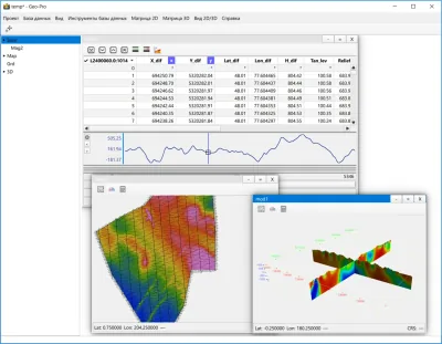
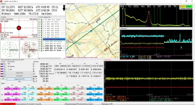
| inversion | 1D and 3D with induced polarisation (IP) effects |
Materials
Photos and documents
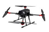
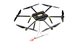
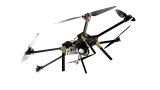
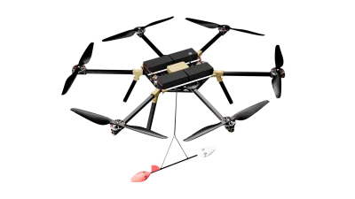
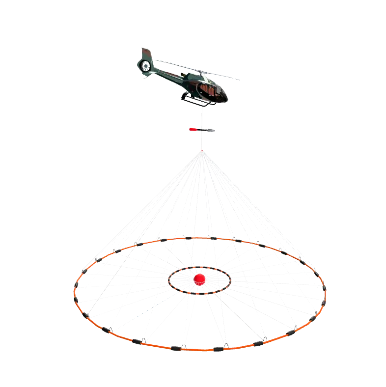
System in flight: the loop below the carrier.